

Design for Manufacturing (DFM) for Plastic Parts: 7 Rules to Cut Tooling Cost and Molding Defects
Most molding defects – sink marks, warpage, sticking – and much of the tooling cost are decided at the part design stage. These 7 DFM rules help make plastic parts easier to tool, faster to mold and more consistent in quality.
A part that looks good in CAD is not always moldable – or it molds only with a complex tool, long cycle time and high scrap. Design for Manufacturing (DFM) means reviewing and adjusting the part design early for the injection molding process. Changing a line in the 3D model costs almost nothing; reworking a finished mold can cost weeks and significant money.
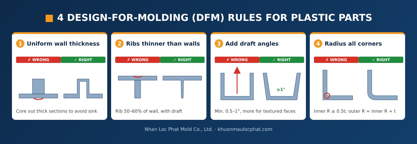
Four basic DFM rules: wrong vs. right design
1. Keep wall thickness uniform
For most consumer parts, nominal walls are typically 1.5–3 mm depending on resin and size. Thick sections cool slowly, causing sink marks, voids and warpage, and cooling time rises roughly with the square of wall thickness. Core out thick areas and use gradual transitions where thickness must change.
2. Design ribs correctly
- Rib thickness about 50–60% of the nominal wall (t).
- Rib height up to about 3t; rib spacing at least 2t.
- Add draft and a root radius of about 0.25–0.5t.
3. Always add draft
- Minimum about 0.5–1° on polished faces.
- Textured faces need more – typically about 1° extra per 0.025 mm of texture depth.
- Increase draft on deep cores and tall walls.
4. Radius all corners
Sharp corners concentrate stress and restrict flow. As a guideline: inner radius ≥ 0.5t and outer radius = inner radius + t, which keeps the wall uniform through the corner.
5. Design bosses properly
- Boss wall about 0.6t, hollow – never solid.
- Boss OD typically 2–2.5 times the screw hole diameter.
- Tie bosses to walls with ribs rather than merging them into thick sections.
6. Minimize undercuts
Undercuts (hooks, side holes, threads) require slides or lifters, adding tooling cost, lead time and maintenance risk. Consider through-holes in the draw direction, redesigned snap fits or a different parting line first.
7. Account for shrinkage and set realistic tolerances
- Semi-crystalline resins, high shrinkage: PP about 1.5–2.5%; PE about 1.5–3%; POM about 1.8–2.5%.
- Amorphous resins, low shrinkage: ABS about 0.4–0.7%; PC about 0.5–0.7%; PMMA about 0.2–0.8%.
Apply tight tolerances only to critical fit dimensions. Unnecessary tight tolerances raise tooling cost, sampling rounds and scrap.
Involve your toolmaker early
Gate location, parting line, weld lines and ejector pin positions all affect part appearance and should be agreed between the product designer and the toolmaker before design freeze, not after T1.
Nhan Loc Phat Mold Co., Ltd. (Ho Chi Minh City, Vietnam) offers DFM reviews, product design in Creo, injection mold design and manufacturing, and contract molding under strict design confidentiality. Send us your drawings or concept for a consultation.
